𐄀 Intelligent Connectivity, Powering the Future


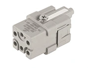
Uninterruptible power supply (UPS) systems rely on reliable electrical connections to deliver backup power, connect battery assemblies, and support communication between system components. Different UPS connector types serve different purposes, and selecting the right interface is essential for equipment compatibility, safe installation, and efficient maintenance.
For UPS manufacturers, power module designers, battery system suppliers, and equipment integrators, understanding the differences between power, battery, and communication connectors helps simplify system integration and reduce avoidable connection problems.
This guide explains the main UPS connector types, where they are used, how modular connector designs support equipment integration, and what to check before choosing a connector for a specific application.

A UPS system may contain several electrical interfaces depending on its architecture, power rating, battery configuration, and monitoring requirements. Rather than using one connector for every function, designers select interfaces according to the electrical and communication requirements of each connection point.
The main categories of UPS connectors include:
Power connectors: Transfer electrical power between UPS modules, internal power circuits, and other equipment.
Battery connectors: Connect battery packs, battery strings, or battery assemblies to the relevant UPS circuits.
Communication connectors: Support data exchange between compatible monitoring, control, and management devices.
Signal connectors: Carry status signals, control signals, and other low-power electrical signals.
Module-to-module connectors: Connect components within modular UPS architectures, where the design may require compact interfaces or blind-mate connections.
These categories describe functional roles rather than mutually exclusive product types. For example, a connector assembly may combine selected power and signal contacts, provided it is specifically designed and rated for those functions.
The correct UPS connector type depends on the equipment architecture and the requirements of the specific interface. Physical compatibility alone does not establish electrical or communication compatibility.
Power connectors are used wherever electrical energy must pass between UPS components or connected equipment. Depending on the system design, these interfaces may appear in power modules, internal power distribution assemblies, bypass modules, and other electrical subassemblies.
When selecting a UPS power connector, engineers should consider several factors.
The connector must meet the specified voltage and current requirements of the intended application. Designers should also verify conductor compatibility, contact resistance, temperature-rise limits, insulation requirements, and the conditions under which the ratings apply.
These parameters should be checked against the manufacturer's technical documentation rather than estimated from the connector's physical size.
UPS equipment often contains closely arranged electrical components and cooling structures. Connector dimensions, mounting orientation, cable exit direction, and access for assembly can therefore influence the overall equipment layout.
For modular power systems, the connector must also match the intended mating interface and remain properly aligned during installation.
Correct mating, secure mounting, and appropriate assembly procedures help support a reliable electrical connection. Designers should review the manufacturer's installation instructions and ensure that inspection and replacement can be performed as required.
A suitable power connector is therefore not simply one that meets the electrical ratings. It must also fit the mechanical design and operating conditions of the UPS equipment.
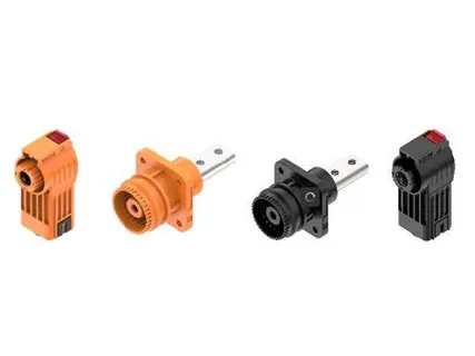
Battery connectors provide the electrical interfaces required to connect battery packs, battery strings, or battery assemblies within a UPS installation. Their configuration varies according to the battery architecture, voltage requirements, current demand, and maintenance strategy.
Battery-side interfaces require careful consideration because they form part of a system designed to supply power when the normal power source is unavailable.
Voltage and current requirements: Confirm the connector ratings for the intended battery circuit and operating conditions.
Polarity and connection arrangement: Verify terminal identification, mating configuration, and the applicable installation procedures.
Contact and conductor compatibility: Check the specified cable size, contact arrangement, and termination method.
Protection and insulation: Confirm the required insulation, enclosure protection, and other safety requirements.
Maintenance requirements: Consider inspection access, replacement procedures, and the need to prevent incorrect connections.
Battery connector selection should follow the battery manufacturer's requirements and the UPS system design. Connectors must not be substituted solely because their dimensions appear similar.
For equipment manufacturers developing integrated backup power systems, coordinating battery interfaces with the wider electrical design helps reduce compatibility issues during assembly and servicing.
Power delivery is only one part of UPS operation. Monitoring and control functions also depend on suitable electrical interfaces between compatible devices.
Communication connectors may be used to connect monitoring equipment, management systems, or other devices that exchange operational data. Signal connectors may support status feedback, control commands, alarms, or other low-power electrical functions.
The exact interfaces depend on the UPS model and the communication architecture. Some systems use established communication standards, while others may require manufacturer-specific interfaces.
When specifying communication and signal connectors, confirm the following:
Supported communication protocol or signal type.
Pin assignments and connector configuration.
Electrical characteristics of the connected devices.
Cable specifications, shielding, and grounding requirements where applicable.
Compatibility with the intended monitoring or control equipment.
A connector that physically fits a communication port may still be unsuitable if the pin assignments or electrical interface differ. Verification against the equipment documentation is therefore essential.
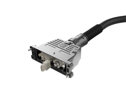
Modular UPS architectures allow equipment designers to arrange power modules and related components within a shared system. In these applications, blind-mate connectors can help establish connections when a module is inserted into its designated position, reducing the need to connect each interface separately by hand.
Depending on the connector design, floating mounting arrangements can accommodate a specified amount of positional misalignment during mating. This can help simplify module installation when the connector, chassis, and mounting structure are designed to work together.
However, blind-mate and floating connectors still have defined alignment limits and mechanical requirements. They should not be assumed to compensate for substantial installation errors or incompatible interfaces.
Before specifying these UPS connector types, engineers should check:
Permitted alignment tolerance and mating travel.
Mounting dimensions and module insertion direction.
Electrical ratings and contact configuration.
Mechanical guidance and retention requirements.
Insertion, withdrawal, inspection, and servicing procedures.
Yonggui Electric offers UPS-related connector solutions that include module power interface designs. For applications requiring compact or modular interfaces, review the product details and confirm the applicable specifications for the intended equipment.
The best connector depends on the function of the interface, the electrical requirements, the equipment layout, and the conditions under which the UPS will operate. A structured review can help engineering and procurement teams compare suitable options.
| Selection Factor | What to Confirm | Why It Matters |
|---|---|---|
| Application | Power, battery, signal, communication, or module connection | Ensures the connector is designed for the intended function. |
| Electrical requirements | Rated voltage, current, contact arrangement, and conductor size | Supports electrical compatibility with the connected equipment. |
| Mechanical interface | Dimensions, mounting, mating direction, and alignment tolerance | Helps prevent installation and mating problems. |
| Environmental conditions | Temperature, humidity, vibration, and required ingress protection | Helps establish suitability for the installation environment. |
| Maintenance | Inspection access, replacement procedures, and component identification | Supports practical servicing throughout the equipment lifecycle. |
| Documentation | Drawings, technical specifications, test records, and applicable compliance requirements | Helps engineering teams verify product suitability before approval. |
For customized or modular UPS equipment, it is useful to review connector requirements with the supplier before finalizing the chassis layout and wiring design. This allows mechanical interfaces, electrical ratings, and assembly requirements to be considered together.
Understanding UPS connector types helps equipment manufacturers and system integrators choose appropriate interfaces for power delivery, battery connections, monitoring, communication, and modular equipment integration.
Power connectors must meet the electrical and mechanical requirements of their applications. Battery connectors require careful attention to ratings, polarity, insulation, and maintenance. Communication and signal interfaces must match the connected devices, while blind-mate designs need suitable alignment and mounting arrangements.
By reviewing these requirements early, UPS manufacturers can reduce avoidable interface mismatches and develop equipment that is easier to assemble, inspect, and maintain.
Yonggui Electric offers UPS-related connector solutions for equipment integration applications. If you are developing a modular UPS, specifying battery interfaces, or reviewing connector options for a new power system, visit the UPS connector solution page and contact the team to discuss your application requirements and technical specifications.
Common categories include power connectors, battery connectors, signal connectors, communication interfaces, and module-to-module connectors. The actual configuration depends on the UPS architecture.
A power connector transfers electrical energy between equipment components, while a battery connector specifically serves an interface involving a battery pack, battery string, or battery assembly.
They support data exchange between compatible monitoring, control, and management devices. The required connector and protocol depend on the system design.
A blind-mate connector is designed to establish a connection as compatible modules are brought together, reducing the need to connect each interface separately by hand.
Confirm the interface function, voltage and current ratings, mechanical dimensions, environmental conditions, compatibility requirements, and relevant technical documentation.


 English
 日本語
 Deutsch
 ไทย
 русский
 العربية