𐄀 Technology Connection to Future
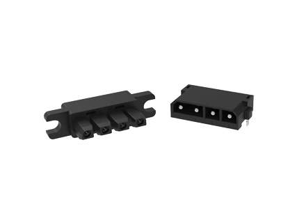
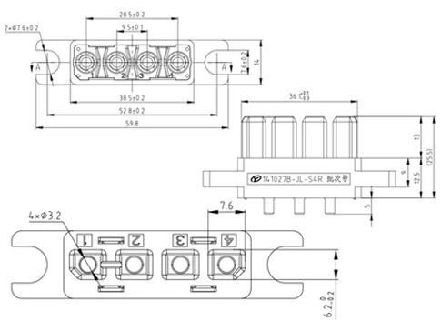
If the tolerance is not noted, press X): ±0.5, X.X: ±0.35, X.XX: ±0.25; Unit: mm
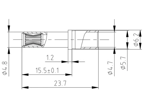
Matching jack(φ3.0, matching number: 4PCS): 141027B-φ3 socket Assembly -6mm²- Silver (114021002249) (Tolerances not noted are ±0.2, unit: mm)
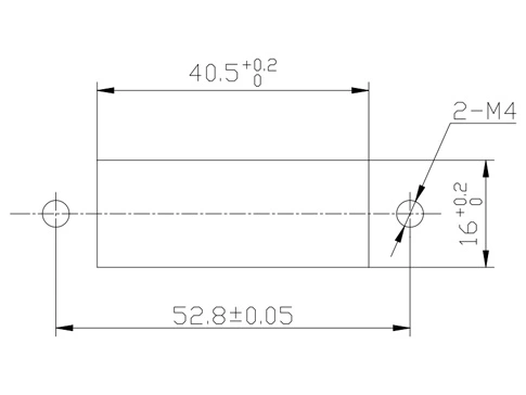
Recommended panel opening size
Parameters | Details | Values |
Electrical Parameter | Rated voltage | 600V AC |
Rated current | 40A (Suitable for 8AWG/10mm² wire) | |
Contact resistance | ≤1mΩ | |
Insulation resistance | ≥3000MΩ (Normality) | |
Withstand voltage | 3000V AC (Sea level) | |
Mechanical Parameter | Mechanical life | ≥100times |
Insertion and extraction force | Insertion force≤54N; Pullout force 12N~54N | |
Pressure plate holding force | ≥400N | |
Single-hole separation force | 3.0N~9.0N | |
Fixation of contact parts) | The axial load is 82N, and the axial displacement of the contact with the shell should not exceed 1mm | |
Environment Features | Connector operating temperature | -55℃~+125℃ |
Storage temperature | 40℃±2℃ | |
Relative humidity | 90%~95%RH | |
Salt spray level | Neutral salt spray 48H, Only contact parts are assessed | |
Vibration | Product frequency 10Hz~500Hz; Acceleration 98m/s2 vibration test after the appearance of no damage; No loosening, displacement, no abnormal insertion and removal; No power outage exceeding 1us | |
Strike | After the 294m/s2 impact test, the appearance of the product is not damaged, loose, shifted, and inserted and removed without abnormal; No electrical interruption exceeding 1us | |
Materials and surface treatment, etc | Insulating body | PBT Black; Flame retardant rating: UL94-V0 |
Back sleeve | High conductivity copper, surface treatment: Silver plating on nickel base | |
Crown spring | Beryllium copper, surface treatment: Silver nickel base, impregnated with 823 protectant | |
Locating pawl | Phosphor copper, surface treatment: Nickel base tinned |
Telecom connectors are prohibited from plugging or unplugging when powered;
The gap between the plug and the receptacle should be less than 2.0mm;
Between the plug and receptacle of the connector, the allowable mating limit guide deviation is 1.8mm, and the guide deviation of the equipment guide rail is required to be less than 1.8mm);
After crimping the connector receptacle socket, a 40mm long straight line must come out from the end before bending the cable to avoid misalignment of the pinhole during insertion, causing damage to the socket.
The connector must be aligned with the guide before insertion to avoid serious damage to the connector when forced insertion without alignment.
The connector socket is a floating installation. After the installation screws are tightened, it is necessary to ensure that the socket can float normally to prevent the socket from being locked by the installation screws, causing the connector head base to be unable to automatically guide, align, and engage.
The connector is not allowed to withstand other forces other than its own contact force during the mating process.
From the time the module enters the guide rail until the module is fully inserted, it is recommended that the entire process be controlled between (3 to 5) seconds.
After the socket is crimped or soldered, the tail must be covered with a heat-shrinkable sleeve to avoid short-circuiting and ignition at the tail. The heat-shrinkable sleeve must be (2±1)mm away from the maximum outer circumferential end face of the socket to prevent the positioning claw from being unable to stuck jack;
When placing the contact (socket) into the corresponding hole of the housing, the contact must be inserted in place and gently pulled back to ensure that the positioning claw is stuck (the contact cannot be pushed out in the axial reverse);
It is recommended that the thickness of the cabinet panel should be at least 1.5mm. Otherwise, the panel may be deformed after repeated insertion or removal;
When the PCB board is immersed in three anti-paint, do not allow the three anti-paint to flow to the surface of the contact in the plug-in interface.
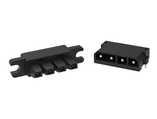

Tailoring connectors to your unique needs.
Provide systemic solutions
Respond to needs within 12 hours