𐄀 Technology Connection to Future
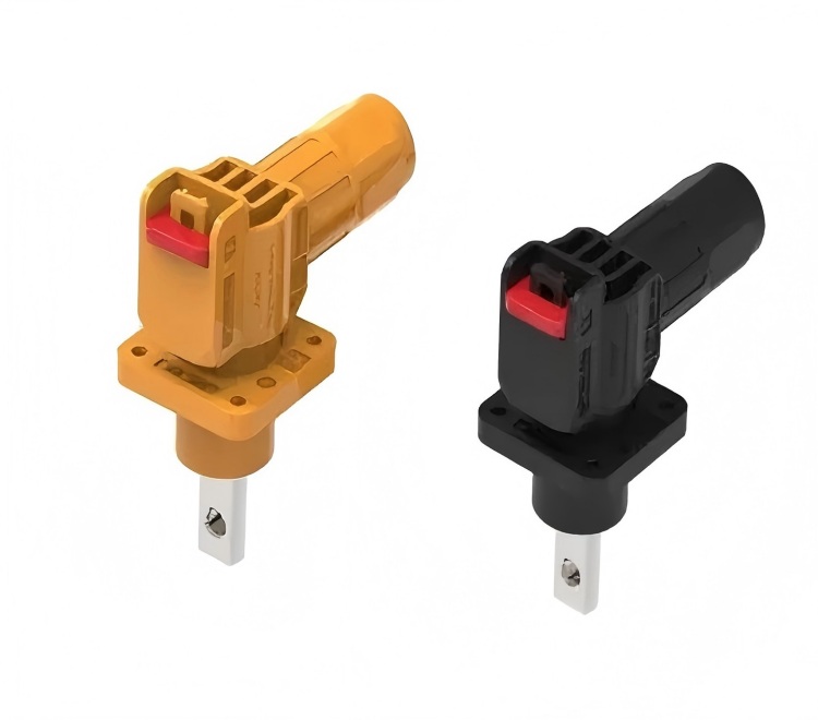


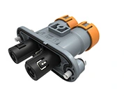
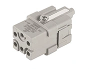
Inside a battery energy storage system, electrical power does not move directly from the battery to the power conversion system through a single path. It passes through battery modules, racks, busbars, cables, protection devices, and multiple connection points before reaching the next stage of the system. Although connectors occupy relatively little space compared with batteries or power conversion equipment, the quality of these connection points can have a direct effect on electrical performance, thermal behavior, installation efficiency, and long-term reliability.
This is where an energy storage connector becomes an important part of BESS design. A connector provides a controlled electrical and mechanical interface between different parts of the system, allowing high-power circuits to be assembled, disconnected, serviced, and reconfigured when required. Depending on the system architecture, connectors may be installed between battery modules, battery racks, DC distribution equipment, cables, and power conversion systems.
Selecting connectors for energy storage therefore involves more than checking a current rating. The electrical path through the contacts, contact resistance, heat generation, insulation system, mechanical retention, environmental protection, and installation method all need to match the actual operating conditions. These considerations become particularly important in systems handling high-voltage DC and substantial current over repeated charge and discharge cycles.
This article examines how the connection works from the electrical and mechanical perspectives, including how current passes through the contact interface, how resistance affects temperature, and what is required to maintain a secure connection throughout BESS operation.
A battery energy storage system converts stored chemical energy into electrical energy when power is delivered to the grid or a connected load. During charging, the electrical flow is reversed. The battery receives DC power through the system's power conversion equipment, while during discharge the battery supplies DC power toward the power conversion system.
Between these major components are several electrical interfaces. A typical architecture can include battery cells assembled into modules, modules installed into racks, rack-level DC connections, DC busbars, protection and switching equipment, and the connection to a power conversion system. Each interface must maintain the intended electrical path while also accommodating the mechanical arrangement of the equipment.
The energy storage connector provides this interface in applications where a detachable connection is useful. Instead of permanently joining every conductor, a connector allows components to be assembled and separated in a controlled way. This can simplify manufacturing, transportation, installation, replacement, and maintenance.
The connector must nevertheless behave much like a continuous conductor once it is mated. Ideally, electrical current should pass through the contact interface with minimal additional resistance. At the same time, the connection needs sufficient mechanical stability to prevent movement, loosening, or accidental separation during operation.
This combination of electrical and mechanical functions distinguishes power connectors from simple cable terminals. In a BESS, the connector becomes part of the system's current path and must be considered together with the cable, busbar, fuse, switchgear, battery module, and PCS rather than as an isolated component.
One of the defining characteristics of battery energy storage applications is the amount of electrical power involved. Depending on the system architecture and application, battery strings and racks can operate at hundreds of volts DC, while larger systems can involve very high continuous and peak currents.
For this reason, connectors for energy storage need an electrical design that considers both voltage and current. Voltage determines requirements such as insulation distance, dielectric performance, and protection against unintended electrical contact. Current has a direct relationship with conductor size, contact resistance, temperature rise, and heat dissipation.
The current does not simply travel through the visible metal body of a connector. It passes through a defined contact system. The conductor is connected to a terminal, the terminal interfaces with a mating contact, and the current continues through the opposite terminal and cable. Every interface in this path contributes to the overall electrical characteristics of the connection.
A connector with an appropriate current rating must therefore maintain acceptable electrical performance under the expected operating conditions. The rating itself should be interpreted together with factors such as conductor size, ambient temperature, enclosure conditions, duty cycle, mating configuration, and installation method.
Temperature is particularly important in high-current DC applications. When current passes through electrical resistance, part of the electrical energy is converted into heat. As current increases, the effect of resistance on heat generation becomes increasingly significant. A connection that appears electrically acceptable under a low-current test may behave differently when subjected to continuous high-current operation.
Connector manufacturers therefore need to consider the entire current path rather than relying only on the nominal current value. Contact geometry, conductive materials, contact force, terminal structure, and heat dissipation all contribute to the final performance of the connection.
The contact interface is one of the most important areas inside an energy storage connector. Two conductive surfaces must remain in reliable electrical contact while the connector is exposed to vibration, temperature changes, repeated mating, and the normal mechanical stresses associated with equipment installation.
Metal surfaces are not perfectly flat at microscopic scale. Even when two surfaces appear to touch completely, the actual electrical current passes through many small areas of physical contact. The design of the contact system determines how effectively these areas carry current and how stable they remain during service.
Contact force is therefore a critical design parameter. Sufficient contact force helps maintain stable electrical contact as environmental and mechanical conditions change. At the same time, the contact system needs to support repeated mating and demating without excessive wear or loss of performance.
Material selection also matters. Conductive materials need to provide suitable electrical conductivity while maintaining mechanical properties and resistance to environmental degradation. Depending on the connector design, the contact surface may also use a plating system intended to improve corrosion resistance, wear performance, or contact stability.
For connectors for energy storage, these details become increasingly relevant when the connector is expected to operate for long periods under repeated charge and discharge cycles. A connector may experience changes in temperature every time the system moves between different load conditions. Over time, these thermal cycles can contribute to mechanical stress within the contact system and surrounding materials.
The result is that connector performance cannot be evaluated solely by looking at the connector housing or terminal dimensions. The quality and stability of the mating interface are equally important.

Electrical resistance is unavoidable in any real-world connection, but excessive resistance at a high-power connector can create an undesirable thermal condition. The relationship is straightforward: when current flows through resistance, heat is generated at the connection.
This makes contact resistance an important parameter when evaluating an energy storage connector. Low and stable contact resistance helps limit unnecessary power loss and reduces localized heating at the interface. More importantly, resistance should remain controlled throughout the expected service life rather than being acceptable only when the connector is new.
Several factors can influence resistance over time. Contact wear can change the effective mating surface. Contamination or oxidation can affect the interface. Mechanical movement can alter contact pressure. Repeated thermal cycling can also influence the mechanical condition of the connection.
Heat management therefore begins with the connector's electrical design but does not end there. The surrounding cable, terminal, enclosure, and ventilation conditions can all affect the temperature of the connector. A connector installed inside a compact battery enclosure may experience a very different thermal environment from the same connector installed in a well-ventilated cabinet.
For system designers, this means connector selection should consider actual operating conditions rather than treating current rating as an independent number. The expected current profile, ambient temperature, enclosure design, cable configuration, and installation arrangement should be evaluated together.
For example, a connector used in a battery rack may carry substantial current continuously, while another connection may experience shorter periods of high current. The appropriate design can differ even if both systems have similar nominal voltage levels.
Maintaining a stable connection also helps reduce the risk of localized heating. In a large BESS, many individual electrical interfaces may exist across multiple racks and cabinets. Consistent connector performance across these interfaces is therefore an important part of overall system reliability.
An electrical connector in a BESS must remain mechanically secure as well as electrically conductive. A connection that carries the required current but can loosen under vibration or installation stress does not provide a reliable system interface.
The locking mechanism is one part of this requirement. Depending on the connector design, a mechanical latch, locking structure, or other retention method can help prevent unintended separation after mating. The connector should provide a clear and repeatable mating condition so that installers can determine whether the connection has been properly engaged.
Strain relief is another important consideration. Cables connected to battery systems can be relatively heavy, and mechanical forces may be transferred to the connector if the cable is not adequately supported. A suitable connector and installation arrangement should prevent unnecessary force from being concentrated at the contact interface.
Insulation is equally important because battery systems involve DC voltages that can present serious electrical hazards. The connector housing, insulation structure, creepage and clearance design, and protection against accidental contact must correspond to the intended voltage and application environment.
Environmental conditions also influence connector design. Battery energy storage equipment can be installed indoors, outdoors, in industrial facilities, or in dedicated containerized systems. Depending on the application, connectors may encounter humidity, dust, temperature fluctuations, vibration, and other environmental stresses.
For this reason, connectors for energy storage are often designed with features intended to improve environmental protection and mechanical durability. The exact protection level and construction should be selected according to the installation environment rather than assumed from the connector category alone.
These requirements also explain why connector selection should take place early in the BESS design process. Changing the connector after the cable routing, enclosure layout, and battery interface have already been finalized can introduce unnecessary mechanical and electrical changes.
The performance of an energy storage connector depends not only on its design but also on how it is installed. Even a well-designed connector can experience problems if the cable is incorrectly prepared, the terminal is improperly assembled, the connector is incompletely mated, or the cable is subjected to excessive mechanical stress.
During installation, the connector and cable should be handled according to the manufacturer's specified assembly method. Cable preparation, terminal crimping, conductor insertion, locking, and inspection all influence the final electrical connection.
Once installed, commissioning provides an opportunity to verify the connection before the BESS enters normal operation. Electrical testing can help identify installation problems, while visual and mechanical checks can confirm that connectors are correctly positioned and secured.
During operation, maintenance teams may also use electrical and thermal inspection methods to identify abnormal connection behavior. A connector showing an unusual temperature increase under comparable operating conditions may warrant further investigation, particularly when the system contains multiple similar connections that can provide a useful comparison.
Maintenance requirements vary according to system design and operating environment. Connectors exposed to vibration, temperature cycling, dust, or moisture may require closer inspection than connections installed in a controlled indoor environment. The maintenance strategy should therefore follow the equipment manufacturer's instructions and the operating conditions of the BESS.
For manufacturers and system integrators, connector selection also needs to fit the practical requirements of production. A connector that is electrically suitable but difficult to assemble repeatedly can create problems during large-scale manufacturing. Ease of mating, cable routing, accessibility, and serviceability can all influence the efficiency of the finished system.
This is one reason the connector should be considered as part of the complete BESS interface rather than simply as a replaceable accessory. Its electrical, mechanical, thermal, and installation characteristics all interact with the surrounding system.
| Requirement | Why It Matters in BESS | What to Evaluate |
|---|---|---|
| Voltage capability | Supports safe operation of high-voltage DC circuits | Insulation system, creepage, clearance, dielectric performance |
| Current capability | Allows the connector to carry the required operating current | Contact design, conductor size, temperature rise, duty cycle |
| Contact resistance | Influences power loss and localized heating | Contact material, contact force, interface stability |
| Mechanical retention | Prevents unintended separation during operation | Locking structure, vibration resistance, mating security |
| Environmental protection | Helps maintain performance under installation conditions | Ingress protection, sealing, temperature and corrosion resistance |
| Serviceability | Supports installation, replacement, and maintenance | Mating cycles, accessibility, assembly method, cable routing |
When evaluating an energy storage connector for a new system, these factors should be considered together. A connector with a suitable electrical rating may still be unsuitable if its mechanical interface does not fit the installation or if its environmental characteristics do not match the operating location.
For BESS manufacturers, system integrators, and equipment designers, this approach can also simplify component selection. Defining the voltage, current, cable configuration, installation environment, mechanical requirements, and expected service conditions first provides a clearer basis for selecting the appropriate connector design. Yonggui Electric, for example, develops electrical connector solutions for applications where reliable power and signal interfaces are required, allowing connector selection to be considered alongside the broader equipment architecture. The company's connector product range provides a starting point for reviewing different application-oriented connection solutions.
Ultimately, the role of connectors in energy storage extends beyond simply joining two cables. The connector becomes part of the electrical path, the mechanical structure, and the service interface of the battery system. Its performance can influence current distribution, thermal behavior, assembly quality, and maintenance over the operating life of the equipment.
An energy storage connector provides the electrical and mechanical interface needed to connect battery modules, racks, distribution equipment, and power conversion systems within a BESS. Because these systems operate with significant DC voltage and current, connector performance depends on more than basic electrical continuity. Contact resistance, contact force, heat generation, insulation, mechanical retention, environmental protection, and installation quality all contribute to the reliability of the finished connection.
For system designers and integrators, choosing suitable connectors for energy storage means evaluating the connector as part of the complete electrical and mechanical system. When voltage, current, thermal conditions, cable configuration, environment, and maintenance requirements are considered together, the connector can provide a stable interface throughout installation and long-term operation.
As BESS architectures continue to develop, connector design will remain closely connected to the practical requirements of higher power density, modular construction, easier service, and reliable DC power transmission. Selecting the connection interface early and matching it to the actual system conditions can help create a more consistent and maintainable energy storage platform. For application-specific connector requirements, engineers can also discuss the system configuration directly through Yonggui Electric's contact page.
An energy storage connector is an electrical connector designed to provide a detachable power connection within a battery energy storage system. It can be used between battery modules, racks, cables, DC distribution equipment, and other parts of the electrical system.
Connectors form part of the system's electrical current path while also providing mechanical retention and serviceability. Their contact resistance, insulation, mechanical stability, and environmental performance can influence the reliability of the BESS.
Key considerations include operating voltage, current, contact resistance, temperature rise, insulation, mechanical retention, cable size, environmental conditions, installation method, and expected service requirements.
Higher contact resistance can increase electrical losses and generate additional heat at the connection point. Stable, controlled contact resistance is therefore important in high-current BESS applications.
Yes. A detachable connector can make certain battery and power connections easier to assemble, disconnect, replace, or service. However, connectors should only be mated or disconnected according to the applicable safety procedures and manufacturer's instructions.
Connectors specifically designed for the intended BESS voltage and current range can be used in high-voltage DC applications. The connector's insulation, contact system, mechanical structure, and environmental protection should all be matched to the actual operating conditions.


 English
  日本語
日本語  Deutsch
  ไทย
ไทย  русский
  العربية